Non-Polarizing
Plate Beamsplitters
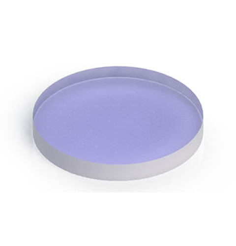
Beamsplitters are often classified according to their construction: cube or plate. A plate beamsplitter is a common type of beamsplitter that is composed of a thin glass substrate with an optical coating optimized for a 45° angle of incident (AOI). Standard plate beamsplitters split incident light by a specified ratio that is independent of the light’s wavelength or polarization state, while polarizing plate beamsplitters are designed to treat S and P polarization states differently.
Advantages of a plate beamsplitter are less chromatic aberration, less absorption due to less glass, smaller and lighter designs compared to a cube beamsplitter. Disadvantages of the plate beamsplitter are the ghost images produced by having light reflected off of both surfaces of the glass, lateral displacement of the beam due to thickness of the glass, difficulty to mount without deformation, and their sensitivity to polarized light.
Our plate beamsplitters have a coated front surface that determines the beam splitting ratio while the back surface is wedged and AR coated. The Wedged Beamsplitter Plate is designed to make multiple attenuated copies of a single input beam.
To help reduce unwanted interference effects (e.g., ghost images) caused by the interaction of light reflected from the front and back surfaces of the optic, all of these plate beamsplitters have an antireflection (AR) coating deposited onto the back surface. This coating is designed for the same operating wavelength as the beamsplitter coating on the front surface. Approximately 4% of the light incident at 45° on an uncoated substrate will be reflected; by applying an AR coating to the back side of the beamsplitter, this percentage is reduced to an average of less than 0.5% at the design wavelength of the coating. In addition to this feature, the back surface of all of our round plate beamsplitters has a 30 arcmin wedge, therefore, the fraction of light that does get reflected from this AR-coated surface will diverge.
Paralight Optics offers plate beamsplitters available both polarizing and non-polarizing models. Standard non-polarizing plate beamsplitters split incident light by a specified ratio that is independent of the light’s wavelength or polarization state, whereas polarizing plate beamsplitters are designed to treat S and P polarization states differently.
Our non-polarizing plate beamsplitters are fabricated by N-BK7, Fused Silica, Calcium Fluoride and Zinc Selenide covering the UV to MIR wavelength range. We also offer beamsplitters for use with Nd:YAG wavelengths (1064 nm and 532 nm). For some information on the coatings of non-polarizing beamsplitters by N-BK7, please check the following graphs fro your references.

Features:
Substrate Materials:
N-BK7, RoHS Compliant
Coating Options:
All Dielectric Coatings
Optical Performance:
Split Ratio Sensitive to Polarization of the Incident Beam
Design Options:
Custom Design Available

Common Specifications:

Reference Drawing for
Non-Polarizing Plate Beamsplitter
Plate beamsplitters consist of a thin, flat glass plate that has been coated on the first surface of the substrate. Most plate beamsplitters feature an anti-reflection coating on the second surface to remove unwanted Fresnel reflections. Plate beamsplitters are often designed for a 45° AOI. For substrates with a 1.5 index of refraction and a 45° AOI, beam shift distance (d) can be approximated using the equation in the left drawing.
Parameters
Ranges & Tolerances
-
Type
Non-polarizing plate beamsplitter
-
Dimension Tolerance
+0.00/-0.20 mm
-
Thickness Tolerance
+/-0.20 mm
-
Surface Quality (Scratch-Dig)
Typical: 60-40 | Precision: 40-20
-
Surface Flatness (Plano Side)
< λ/4 @632.8 nm per 25mm
-
Parallelism
< 1 arcmin
-
Chamfer
Protected < 0.5mm X 45°
-
Split Ratio (R/T) Tolerance
±5%, T=(Ts+Tp)/2, R=(Rs+Rp)/2
-
Clear Aperture
> 90%
-
Coating (AOI=45°)
Partially reflective coating on the first (front) surface, AR coating on the second (back) surface
-
Damage Threshold
>5 J/cm2, 20ns, 20Hz, @1064nm

Graphs
For more information on other types of plate beamsplitters such as wedged plate beamsplitters (5° wedge angle to separate multiple reflections), dichroic plate beamsplitters (exhibiting beamsplitting properties that are wavelength dependent, including longpass, shortpass, multi-band, etc.), polarizing plate beamsplitters, pellicle (without chromatic aberration & ghost images, providing excellent wavefront transmission properties and being the most useful for interferometric applications) or polka dot beamsplitters (their performance being not angle dependent) both of which can cover wider wavelength ranges, please contact us for details.

50:50 Non-Polarizing Plate Beamsplitter @450-650nm at 45° AOI

50:50 Non-Polarizing Plate Beamsplitter @650-900nm at 45° AOI