
1 Definition and causes of subsurface damage
The Sub-surface damage of optical components (SSD, sub-surface damage) is usually mentioned in high-precision optical applications such as intense laser systems and lithography machines, and its existence restricts the final processing accuracy of optical components and further affects the imaging performance of optical systems, so it needs to be paid enough attention. Subsurface damage is usually characterized by cracks inside the surface of the element and internal stress layers, which are caused by some residual fragmentation and deformation of the material composition in the near surface area. The subsurface damage model is shown as follows: the top layer is the polished sediment layer, and then the crack defect layer and stress deformation layer are the bottom layer, and the material layer without damage is the innermost layer. Among them, the crack defect layer and the stress deformation layer are subsurface damage.
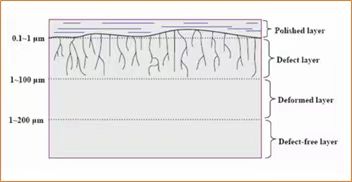
Subsurface damage model of optical materials
Optical components of the material is generally glass, ceramics and other hard and brittle materials, in the early processing stage of the components, need to go through milling molding, fine grinding and rough polishing processes, in these processes, mechanical grinding and chemical reactions exist and play a role. The abrasive or abrasive tool in contact with the surface of the element has the characteristics of uneven particle size, and the force of each contact point on the surface of the element is not uniform, so the convex and concave layer and the internal crack layer will be produced on the glass surface. The material present in the cracked layer is the component that has broken during the grinding process, but has not fallen off the surface, so sub-surface damage will be formed. Whether it is abrasive grinding of loose particles or CNC grinding, this phenomenon will be formed on the surface of the material. The actual effect of sub-surface damage is shown in the following figure:
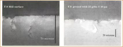
Subsurface damage rendering
2 Subsurface damage measurement methods
Since sub-surface damage cannot be ignored, it must be effectively controlled by optical component manufacturers. In order to effectively control it, it is necessary to accurately identify and detect the size of the subsurface damage on the surface of the component, since the early part of the last century, people have developed a variety of methods to measure and evaluate the size of the subsurface damage of the component, according to the mode of the degree of influence on the optical component, it can be divided into two categories: destructive measurement and non-destructive measurement (non-destructive testing).
Destructive measurement method, as the name suggests, is the need to change the surface structure of the optical element, so that the sub-surface damage that is not easy to observe can be revealed, and then use a microscope and other instruments to observe the measurement method, this method is usually time-consuming, but its measurement results are reliable and accurate. Non-destructive measurement methods, which do not cause additional damage to the component surface, use light, sound, or other electromagnetic waves to detect the subsurface damage layer, and use the amount of property changes they occur in the layer to assess the size of the SSD, such methods are relatively convenient and quick, but usually a qualitative observation. According to this classification, the current detection methods for sub-surface damage are shown in the figure below:
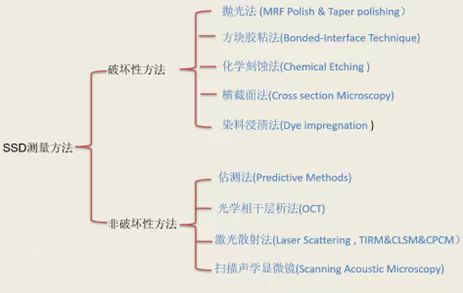
Classification and summary of subsurface damage detection methods
A brief description of these measurement methods follows:
A. Destructive methods
a) Polishing method
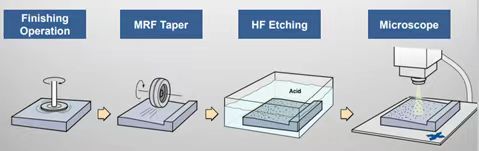
Before the appearance of magnetorheological polishing, optical workers usually used Taper polishing to analyze the sub-surface damage of optical components, that is, cutting the optical surface along an oblique Angle to form an oblique internal surface, and then polishing the oblique surface. It is generally believed that polishing will not aggravate the original sub-surface damage. The cracks of the SSD layer will be more obviously revealed through the immersion corrosion with chemical reagents. The depth, length and other information of the sub-surface damage layer can be measured by optical observation of the inclined surface after immersion. Later, scientists invented the Ball dimpling method (Ball dimpling), which is to use a spherical polishing tool to polish the surface after grinding, throwing a pit out, the depth of the pit needs to be as deep as possible, so that the analysis of the side of the pit can obtain the subsurface damage information of the original surface.
Common methods for detecting subsurface damage of optical elements
Magnetorheological polishing (MRF) is a technique that uses a magnetic fluid strip to polish optical components, which is different from traditional asphalt/polyurethane polishing. In the traditional polishing method, the polishing tool usually exerts a large normal force on the optical surface, while Mr Polishing removes the optical surface in the tangential direction, so Mr Polishing does not change the original sub-surface damage characteristics of the optical surface. Therefore, Mr Polishing can be used to polish a groove on the optical surface. Then the polishing area is analyzed to evaluate the size of the subsurface damage of the original optical surface.
a) Block gluing method
This method has also been used to test sub-surface damage. In fact, select a square sample with the same shape and material, polish the two surfaces of the sample, and then use adhesive to glue the two polished surfaces of the sample together, and then grind the sides of the two samples together at the same time. After grinding, chemical reagents are used to separate the two square samples. The size of the subsurface damage caused by the grinding stage can be evaluated by observing the separated polished surface with a microscope. The process schematic diagram of the method is as follows:
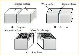
Schematic diagram of subsurface damage detection by block adhesive method
This method has certain limitations. Because there is a sticky surface, the situation of the sticky surface may not fully reflect the actual subsurface damage inside the material after grinding, so the measurement results can only reflect the SSD situation to a certain extent.
a) Chemical etching
The method uses suitable chemical agents to erode the damaged layer of the optical surface. After the erosion process is completed, the subsurface damage is evaluated by the surface shape and roughness of the component surface and the index change of the erosion rate. Commonly used chemical reagents are hydrofluoric acid (HF), ammonium hydrogen fluoride (NH4HF) and other corrosive agents.
b) Cross section method
The sample is dissected and a scanning electron microscope is used to directly observe the size of the subsurface damage.
c) Dye impregnation method
Because the surface layer of the ground optical element contains a large number of microcracks, dyes that can form a color contrast with the optical substrate or contrast with the substrate can be pressed into the material. If the substrate consists of a dark material, fluorescent dyes can be used. Sub-surface damage can then be easily checked optically or electronically. Because the cracks are usually very fine and inside the material, when the penetration depth of the dye penetration is not enough, it may not represent the true depth of the microcrack. In order to obtain the crack depth as accurately as possible, a number of methods have been proposed for impregnating dyes: mechanical prepressing and cold isostatic pressing, and the use of electron probe microanalysis (EPMA) to detect traces of dye at very low concentrations.
B, non-destructive methods
a) Estimation method
The estimation method mainly estimates the depth of sub-surface damage according to the size of the particle size of the abrasive material and the size of the surface roughness of the component. Researchers use a large number of tests to establish the corresponding relationship between the particle size of the abrasive material and the depth of the sub-surface damage, as well as the matching table between the size of the surface roughness of the component and the sub-surface damage. The subsurface damage of the current component surface can be estimated by using their correspondence.
b) Optical Coherence Tomography (OCT)
Optical coherence tomography, the basic principle of which is Michelson interference, evaluates the measured information through the interference signals of two beams of light. This technique is commonly used to observe biological tissues and give cross-sectional tomography of the subsurface structure of the tissue. When OCT technique is used to observe the subsurface damage of optical surface, the refractive index parameter of the measured sample must be considered to obtain the actual crack depth. The method can reportedly detect defects at a depth of 500μm with a vertical resolution of better than 20μm. However, when it is used for SSD detection of optical materials, the light reflected from the SSD layer is relatively weak, so it is difficult to form interference. In addition, surface scattering will also affect the measurement results, and the measurement accuracy needs to be improved.
c) Laser scattering method
Laser irradiation on the photometric surface, using the scattering properties of the laser to assess the size of the subsurface damage, has also been extensively studied. Common ones include Total internal refection microscopy (TIRM), Confocal laser scanning microscopy (CLSM), and intersecting polarization confocal microscopy (CPCM). cross-polarization confocal microscopy, etc.
d) Scanning acoustic microscope
Scanning acoustic microscopy (SAM), as an ultrasonic detection method, is a non-destructive testing method that is widely used to detect internal defects. This method is usually used to measure samples with smooth surfaces. When the surface of the sample is very rough, the measurement accuracy will be reduced due to the influence of surface scattered waves.
3 Subsurface damage control methods
It is our ultimate goal to effectively control the subsurface damage of optical components and obtain components that completely remove SSDS. Under normal circumstances, the depth of sub-surface damage is proportional to the size of the abrasive particle size, the smaller the particle size of the abrasive, the shallower the sub-surface damage, therefore, by reducing the granularity of grinding, and fully grinding, you can effectively improve the degree of sub-surface damage. The processing diagram of sub-surface damage control in stages is shown in the figure below:
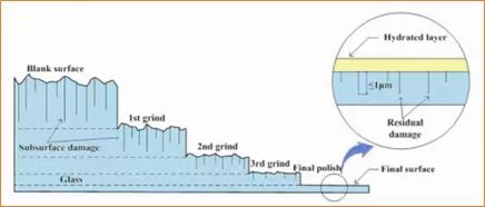
Subsurface damage is controlled in stages
The first stage of grinding will fully remove the subsurface damage on the blank surface and produce a new subsurface in this stage, and then in the second stage of grinding, it is necessary to remove the SSD generated in the first stage and produce new subsurface damage again, processing in turn, and control the particle size and purity of the abrasive, and finally obtain the expected optical surface. This is also the processing strategy that optical manufacturing has followed for hundreds of years.
In addition, after the grinding process, pickling the surface of the component can effectively remove the sub-surface damage, thereby improving the surface quality and improving the processing efficiency.
Contact:
Email:jasmine@pliroptics.com ;
Phone/Whatsapp/Wechat:86 19013265659
web:www.pliroptics.com
Add:Building 1, No.1558, intelligence road, qingbaijiang, chengdu, sichuan, china
Post time: Apr-18-2024


