
1 Performance parameters after coating
In the previous article, we introduced the functions, principles, design software and common coating techniques of optical thin films. In this article, we introduce the testing of post-coating parameters. The performance parameters of the surface of the component after coating include the Transmittance (Transmittance), Reflectance (R), Absorptance (A), etc. In addition, the absorptance (Transmittance) and so on. The scattering characteristic S (Scatter) of the film surface also needs to be tested and analyzed.
The transmittance T is the ratio of the light intensity energy passing through the film to the incident light energy. The reflectance R is the ratio of the intensity energy reflected by the surface of the coating to the incident energy. Absorption A is the ratio of the light energy absorbed by the film layer to the incident light energy. For these three parameters, the following relationships exist:
T + R + A = 1
That is, the sum of the transmittance, reflectivity and absorption of the film layer is the constant 1. This means that after the light beam passes through the membrane, part of it is passed through, part of it is reflected away, and the rest is absorbed by the membrane.
On the optical component drawings, the transmittance or reflectivity of the film surface is usually required, and the spectral range and incidence Angle under the application state need to be defined clearly. If polarization is also required, the range of polarization states needs to be clearly defined. As an example, the coating requirements in the figure below are that at 770nm, the reflectivity needs to be no less than 88% at 45 degree incidence, and at 550nm, the transmittance needs to be no less than 70% at 45 degree incidence.

In addition to the above optical properties, the mechanical and chemical properties of the optical film layer also need to be considered, including the wear resistance, firmness, solubility of the film layer. In addition, the quality of the optical surface after coating also needs to be considered, including the requirements for pitting, scratches, dirt, stains, etc.
2 Principle of spectrophotometer
In this paper, we focus on the optical properties of the film test methods to introduce, in practice, the main Spectrophotometer (Spectrophotometer) and Ellipsometer (Ellipsometer) to test the film parameters, spectrophotometer can test the transmittance, reflectivity and absorption characteristics of optical products. The ellipsometer can measure the thickness and polarization characteristics of the film layer, and the principle of both is similar.
The structure of such a device can be divided into two parts of the beam generation channel and the beam receiving channel, when the transmittance of the component needs to be tested, the component is placed in the middle of the two channels, so that the beam passes through the sample, when the reflectivity of the component needs to be tested, the component is placed on the same side of the two channels, so that the beam is reflected by the sample. As an example, the principle of a spectrophotometer to measure the transmittance of a sample is shown in the following figure:
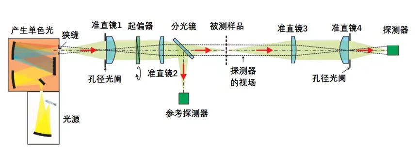
In the figure above, the left end is the beam generation channel, using a wide spectrum light source to emit light, and then through the splitting of the grating and the selection of the slit, output a specific wavelength of light, the beam passes through the collimator 1, becomes a collimated beam, and then passes through the polarizer that can rotate the Angle, becomes a polarized light, and the polarized light is divided into 2 beams by the spectroscope after the collimator 2 is gathered. A light beam is reflected into the reference detector, where the collected light beam is used as a reference to correct the energy drift due to the fluctuations of the light source, and another light beam passes through the sample, is reshaped by collimator 3 and collimator 4, and enters the detector at the far right end of the test. In the actual test, two energy values are obtained by putting in and taking out the tested sample, and the transmittance of the sample can be obtained by comparing the energy.
The principle of the ellipsometer is similar to the principle of the above spectrophotometer, except that a rotating 1/4 wave plate is added as a compensation element in the beam sending channel and the receiving channel, and a polarizer is also added in the receiving channel, so that the polarization characteristics of the sample can be analyzed more flexibly. In some cases, the ellipsometer will also directly use a wide spectrum light source, and adopt a slit and splitter spectrometer at the receiving end, combined with a linear array detector, to achieve the performance test of the component.
3. Test of transmittance
In the transmittance test, in order to avoid the reflection of the detector receiving the light beam, the integrating sphere is often used as the receiver, the principle is shown as follows:
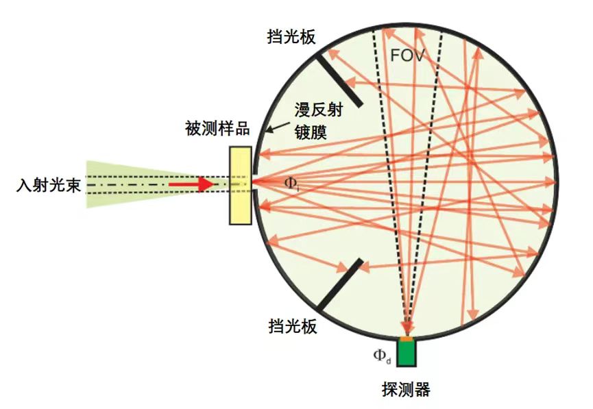
As can be seen from the above figure, the integrating sphere is a cavity sphere coated with white diffuse reflection coating material on the inner wall, and there is a window hole on the ball wall, which is used as the light hole of the incident light and the receiving hole of the light detector. In this way, the light entering the integrating sphere is reflected several times through the inner wall coating, forming a uniform illuminance on the inner wall, and is received by the detector.
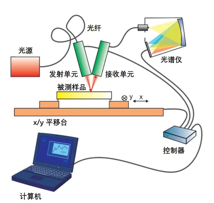
As an example, the structure of a device used to test the transmittance of an optical plate is shown below
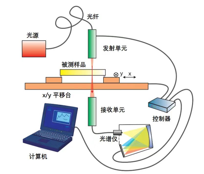
In the figure above, the tested sample is placed on an adjustment table that can be shifted in the x and y directions. The transmittance of the sample can be tested at any position by computer control of the adjustment table. The transmittance distribution of the whole flat glass can also be obtained by scanning test, and the resolution of the test depends on the spot size of the beam.
4. Reflectivity test
For the measurement of optical film reflectivity, there are usually two ways, one is relative measurement and the other is absolute measurement. The relative measurement method requires a reflector with known reflectance to be used as a reference for comparison testing. In practice, the reflectance of the reference mirror needs to be calibrated regularly with the aging or contamination of the film layer. Therefore, this method has potential measurement errors. The method of absolute reflectivity measurement requires the calibration of the reflectivity of the test device without placing the sample. In the figure below, the structure of the classic V-W device is given to achieve the absolute measurement of the reflectivity of the sample:
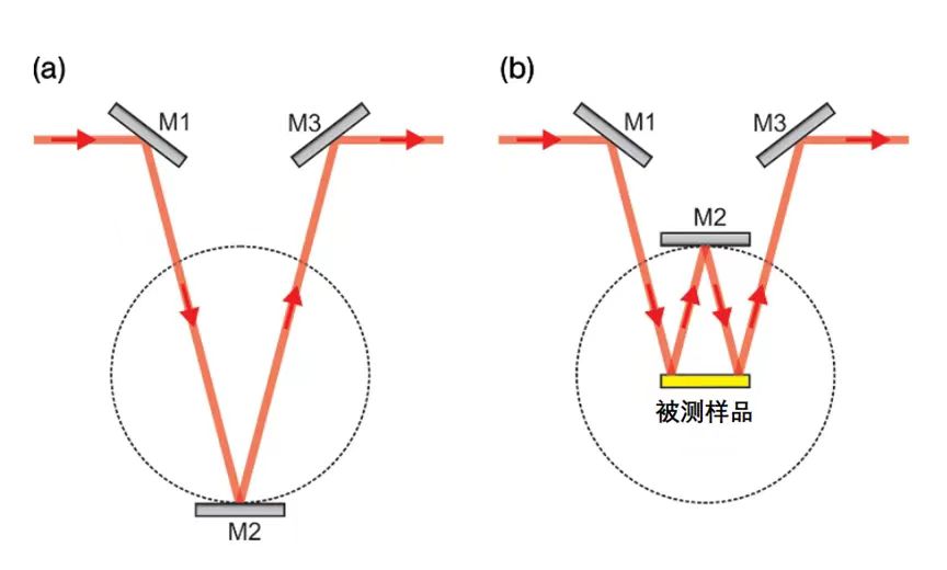
The left figure in the above figure shows a V-shaped structure consisting of three mirrors, M1, M2 and M3. First, the light intensity value in this mode is tested and recorded as P1. Then, in the right figure, the sample under test is put in, and the M2 mirror is rotated to the top position to form a W-shaped structure. The absolute reflectivity of the measured sample can be obtained. This device can also be improved, for example, the sample under test is also equipped with an independent rotating table, so that the sample under test can be rotated to any Angle, by rotating the M2 mirror to the corresponding reflection position, to achieve the beam output, so that the reflectivity of the sample can be tested at multiple angles.
As an example, the structure of a device used to test the reflectivity of an optical plate is shown below:
In the figure above, the tested sample is placed on the x/y translation adjustment table, and the reflectivity of the sample can be tested at any position through the computer control of the adjustment table. Through the scanning test, the reflectance distribution map of the whole flat glass can also be obtained.
Contact:
Email:jasmine@pliroptics.com ;
Phone/Whatsapp/Wechat:86 19013265659
web:www.pliroptics.com
Add:Building 1, No.1558, intelligence road, qingbaijiang, chengdu, sichuan, china
Post time: Apr-23-2024


